전정신경염, 전정병증 진단에 있어 전정유발근전위의 제한점과 장비 개발 방향에 대한 제언
Clinical Application and Updates on Vestibular Evoked Myogenic Potential: Proposal for Future Development in Vestibulopathy
Article information
 , 김진일
, 김진일Trans Abstract
Both cervical vestibular evoked myogenic potential (cVEMP) and ocular VEMP (oVEMP) are irreplaceable tools in the current vestibular science, but they have many drawbacks. For example, the test-retest reliability of the asymmetry ratio is inadequate for both tests. The American Academy of Neurology noted that there is insufficient evidence to determine whether cVEMP and oVEMP can accurately identify vestibular function specifically related to the saccule/utricle. One of the most important factors underlying the variability of cVEMP seems to be the control of, and compensation for, baseline muscle contraction power. Reasons for variability in oVEMP include a poor signal to noise ratio, the angle of superior gaze, effective and controlled presentation of stimuli, intracranial pressure, and electrode location. Many of these shortcomings could be improved by further development of recording methods and devices. This article examines the reasons for the insufficient reliability of VEMP and proposes avenues for improvement of VEMP recording systems.
INTRODUCTION
Prior to the introduction of the vestibular evoked myogenic potential (VEMP) test in 1964 [1], there were no vestibular tests that could readily evaluate saccular function in vestibular clinics. With the development of cervical VEMP (cVEMP) and ocular VEMP (oVEMP), it is now possible to evaluate utricular and saccular function separately. After 50 years of experience with VEMP, it is time to re-evaluate the true clinical strengths and shortcomings of this vestibular test. Unfortunately, the midterm evaluation outcomes are not favorable. The recent American Academy of Neurology guidelines noted that there is insufficient evidence to determine whether cVEMP and oVEMP can accurately identify vestibular function specifically related to the saccule/utricle, and whether either of these tests is useful for diagnosing vestibulopathy [2]. Some researchers and clinicians have also pointed out that VEMP outcomes are sometimes inconsistent with those of other well-known vestibular function tests. VEMP seems to have considerable rates of false-positive and -negative results. This article examines the reasons for the insufficient reliability of VEMP and proposes avenues for improvement of VEMP recording systems.
TEST-RETEST VARIABILITY OF VEMP
Poor test-retest reliability is one reason for variability of VEMP. The intraclass correlation coefficients (ICCs) of cVEMP reported in the literature are excellent, ranging from 0.81 to 0.96 [3,4]. However, this should be interpreted with caution because most of the reported excellent ICCs are based on the interpeak amplitude (IPA) of cVEMP. Similar to the maximum slow-phase velocity of caloric response, the unilateral IPA itself is not informative. The cVEMP IPA is informative only when the left/right difference is compared as an asymmetry ratio (AR). Clinically, the AR is more important than the IPA, but the ICC of AR has not been emphasized in the literature. The ICC of AR is reported to be 0.61–0.67, which is only fair to good [3,4]. In our experience, it can be as low as 0.48 under some recording conditions [4]. It seems that the IPA of each ear is reproducible, but the test-retest reliability of cVEMP becomes inadequate when the IPAs are compared between the two ears. The small variability of IPA is assumed to be amplified when recorded twice (left and right) and substituted into the functional equation for AR [AR=(right IPA– left IPA)/(right IPA+left IPA)×100] [5]. The ICC of oVEMP AR has also been reported to be low, and to vary over a wide range of 0.50–0.84, with the ICC of oVEMP IPA being slightly better (0.79–0.87) [6].
VARIABILITY OF cVEMP
One of the most important factors underlying the variability of cVEMP seems to be the control of, and compensation for, baseline muscle contraction power. As cVEMP is an inhibitory response of the contracting muscle, the amplitude of cVEMP shows a strong positive correlation with the baseline contraction power of the recorded muscle [7]. There are two approaches to solve this problem. First, we may perform normalization by allowing for differences between left and right baseline muscle contraction power during recording, but compensate for these differences after recording [8,9]. Second, feedback involves monitoring and strictly controlling the baseline muscle contraction power during recording so that there is no difference in values between the left and right sides [5,10]. Most of the evoked response systems provide normalization and/or feedback functionality. However, both strategies have a number of limitations. For normalization, both mean rectified electromyography (EMG) and root mean squared EMG power have been used to represent the baseline muscle contraction power. However, our experiments indicated that normalization does not offer a complete solution [9]. For example, the normalization algorithm cannot correct for the difference between left and right baseline muscle contraction power during recording when it is very large (asymmetry>44.8%). More importantly, when there is almost no difference (asymmetry<22.5%) between the left and right baseline muscle contraction power, the additional mathematical procedure (i.e., normalization) may increase the normative range of AR, resulting in more variability in the outcome. Thus, there seems to be a trade-off in that the normalization process may correct some degree of difference between left and right baseline muscle contraction power, but at the cost of slightly greater variability and a wider range of normative criteria. It may be recommended to apply an ideal muscle contraction method or position that can guarantee symmetrical baseline muscle contraction power, and to use the normalization procedure only in special cases. For example, the supine position with elevation of the head in the center, can be proposed as a good position for contraction of both sternocleidomastoid (SCM) muscles at the same time, and with the same magnitude.
For feedback, despite efforts to match the bilateral baseline muscle contraction power, some degree of variation between left and right baseline muscle contraction power is inevitable. Conventional unilateral sequential recoding is problematic, because the muscle contraction power cannot be perfectly matched during the first (left) and second (right) recordings. Even if feedback is applied and normalization is performed, there may still be issues, such as muscle fatigue and/or learning effects (e.g., finding a more comfortable but different position/technique during the second run to contract the muscle up to the same root-mean-square [RMS] power) [3,10]. Using this technique, the 2 recordings being compared were made at 2 different time points, no matter what. Some groups have introduced bilateral simultaneous recording [11,12]. It is generally accepted that cVEMP is an ipsilateral response with minimal crossover [13]. Accordingly, the response from each SCM muscle will represent the otolith function of each ear separately, even if the stimuli are presented, and responses are acquired, at the same time. Bilateral simultaneous recording is not only time-efficient (theoretically requiring half as much time) and less effortful from the subjects’ perspective, but it can also provide better test-retest reliability [4]. We reported that the ICC of cVEMP AR was 0.48 with unilateral sequential recording, but this was improved to 0.69 by simply applying the bilateral simultaneous recording technique [4].
Bilateral simultaneous cVEMP recording represents one solution to this baseline muscle contraction power problem, but it has other issues. The first issue is signal crossover of cVEMP. Some subjects show an additional excitatory reflex on the contralateral side of the SCM (n12–p20 signal) [14]. Bilateral simultaneous recording requires cVEMP to be a strictly ipsilateral response with no crossover, and neural circuits with crossover to the contralateral side of the SCM will undermine the usefulness of bilateral simultaneous cVEMP. Volume conduction of the cVEMP signal is the second major challenge. Many groups advocate that the cVEMP response should only be recorded on the ipsilateral side of the neck. In our experience, however, a smaller p13–n23 signal can also be recorded on the contralateral side of the neck in some subjects (Fig. 1). As surface electrodes are usually used for cVEMP recording, strong myogenic electrical activity of the SCM muscle can spread throughout the skin and soft tissue. This electrical spread (volume conduction) can also be detected on the contralateral side. Considering the latency and amplitude of this contralateral signal, it is likely that the contralateral p13–n23 signal originates from the ipsilateral SCM muscle. Volume conduction may be more problematic in younger subjects with higher muscle power and thin skin/soft tissue.

Example of electrical spread of cervical vestibular evoked myogenic potential signals to the contralateral neck. Air-conducted sound was presented to the left ear. A typical p13–n23 response was recorded from the ipsilateral neck. A similar but smaller signal was also recorded in the contralateral neck. This signal probably originated from the ipsilateral neck but spread to the contralateral side due to volume conduction. SCM, sternocleidomastoid.
PROPOSAL FOR BETTER cVEMP RECORDING
Taking the problems outlined above into consideration, this article proposes bilateral simultaneous alternating cVEMP recording with needle EMG electrodes as an avenue for future development (Fig. 2). As mentioned above, unilateral sequential recording cannot guarantee completely identical bilateral baseline muscle contraction power. In addition, even with the best methods, such as normalization and feedback, this problem cannot be resolved sufficiently to yield an acceptable ICC of AR. On the other hand, bilateral simultaneous recording is not free from the issues associated with contamination by contralateral stimulatory neural circuits and volume conduction. To combine the advantages of the 2 recording methods, we can record the cVEMP from the left and right SCM muscles alternately during a single recording session; that is, we can stimulate the left ear and record from the left SCM muscle during the first sweep, and then stimulate the right ear and record from the right SCM muscle during the second sweep. This left/right alternating recording can be continued for up to 100–200 sweeps for each ear. As left/right cVEMP recording is performed during a single session, the baseline muscle contraction conditions/environment are identical. Feedback from the RMS power may still be needed to confirm the symmetrical muscle contraction power, but issues such as muscle fatigue or learning effects could be avoided.
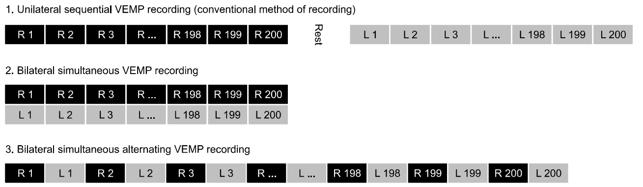
Concept of bilateral simultaneous alternating cervical vestibular evoked myogenic potential (cVEMP) recording. Unilateral sequential VEMP recording is the most commonly used method for averaging the myogenic response. Using this method, the baseline muscle contraction power may be different because one ear is recorded first, and the other later. Bilateral simultaneous VEMP recording is another method in which the recording time is reduced and the test-retest reliability can be improved. But, bilateral simultaneous recording is not free from the issues associated with contamination by contralateral stimulatory neural circuits and volume conduction. Bilateral simultaneous alternating VEMP recording is proposed as a novel alternative method. The baseline conditions/environment of muscle contraction will be identical between the left and right sides. Issues such as muscle fatigue or learning effects could be avoided.
In addition, instead of the surface electrode, a small needle may be positioned within the SCM muscle by penetrating the overlying skin. Direct contact of the active electrode and SCM muscle may result in a better signal to noise ratio (SNR), yielding a sharp p13–n23 signal with less signal amplification and muscle contraction. Needle EMG is a minimally invasive recording method used in the fields of Rehabilitation Medicine and Neurology. This method is slightly more invasive than use of a surface electrode, but is generally well-tolerated by patients.
VARIABILITY OF oVEMP
The reasons for variability of oVEMP may be different from those for variability of cVEMP. As oVEMP is a stimulatory response [15], it is not necessary to take baseline muscle contraction power into consideration. Instead, factors such as poor SNR, the angle of superior gaze, effective and controlled presentation of stimuli, intracranial pressure, and location of the electrode should be considered.
While the amplitude of cVEMP is large (100–200 μV) that of oVEMP is quite small (2–5 μV) [14,16]. In addition, due to its small size, it is sometimes difficult to distinguish the signal from randomly fluctuating noise. A larger n10–p15 signal can be recorded by sustaining the gaze superiorly [16,17]. However, sustaining the angle of gaze can be difficult in some cases and, even in a normal subject, the amplitude of n10–p15 can differ depending on the angle of gaze.
It is also known that a strong bone conduction stimulus can elicit a robust oVEMP response. However, the conventional bone vibrator (Radioear B-71 in most clinics) is generally too weak to deliver sufficient linear acceleration to the skull. Small changes in the location, direction or force of B-71 on the mastoid can also cause substantial changes in the applied linear accelerations [18,19]. For these reasons, strong minishakers, such as Exciter Type 4810 (Brüel & Kjær Sound & Vibration, Nærum, Denmark), have been used [19,20]. Although minishakers can drive a bigger force of up to 10 N at various frequencies (DC to 19 kHz), these devices are not optimized for oVEMP and have not received regulatory approval in all countries. Coupling between the minishaker and the skull is a major problem; as the minishaker was not designed to be attached to the skull, there are no suitable adaptors for binding them. Inadequate coupling will result in variable stimulation intensity and lead to poor test-retest reliability.
The position of the head relative to the body may also have an influence on the oVEMP amplitude, according to changes in intracranial pressure. Lowering the intracranial pressure (i.e., by placing the head higher than the body) may be beneficial for acquiring n10–p15 signals with larger amplitude [21].
The locations of the active and reference electrodes should also be controlled. It may be difficult to consistently align the four electrodes (right active, right reference, left active, and left reference) in all patients. In current practice, conventional circular surface electrodes are placed below the eyes. However, the circular electrode is usually too large, and it may be placed too far away from the interior oblique muscle (the origin of oVEMP), thus resulting in a smaller n10–p15 amplitude. When a second (reference) electrode is placed below the first (active) electrode, the sticker may cover the mouth angle in subjects with small faces. Other labs prefer to cut the electrode so that the conductive solid gel in the core can be placed closer to the inferior oblique muscle. However, manually cutting the electrode with scissors may also lead to variability. The horizontal alignment may also be an issue. As we cannot directly observe the inferior oblique muscle, the electrode is usually placed below the center of the palpebral fissure. The positions of the electrode can sometimes be asymmetrical. If one of the bilateral electrodes is placed closer to the inferior oblique muscle compared to the other side, this may also result in an asymmetrical response.
PROPOSAL FOR BETTER oVEMP RECORDING
Bilateral simultaneous alternating recording may also be beneficial to control the variability of oVEMP. If the bilateral oVEMP is recorded in a single session, the superior gaze angle, intensity of the stimuli, and intracranial pressure would be identical between the recordings in the left ear and right ear. Contamination by contralateral stimulatory neural circuits and volume conduction issues may also be resolved by the alternating technique.
With regard to the superior gaze angle, a laser pointer embedded in the forehead module may be used to control the angle of gaze [21]. The conventional method (marking a static visual target on the ceiling) may not be a good solution, as the height differs among subjects and the head can continue to move during oVEMP recording. The laser module is fixed to the head, which allows a consistent amount of superior gaze regardless of head movement, neck flection, and the height of the subject.
A strong but intensity-controlled bone vibrator designed for oVEMP use would greatly contribute to consistent oVEMP results. At present, there are no evoked response systems equipped with a bone vibrator intended for abrupt linear acceleration of the skull. The bone vibrator should be attached to an elastic head strap to achieve stable coupling with the skull (Fig. 3). The strength/stability of coupling can be monitored by 2 methods. First, a pressure gauge can be embedded in the forehead module so that the elastic power of the head strap can be measured and controlled. This technique was proposed by our group to test the stability of the video head impulse test system during abrupt head movements [22]. Strong elastic power with high pressure (>45 mmH2O) will lead to stable coupling with less variability. The second method is to apply an additional accelerometer that can monitor the intensity of linear acceleration. The monitoring accelerometer can be placed on the side of the skull to ensure sufficient transduction of acceleration to the ear area. Alternatively, it can be placed on the back of the head (occiput), depending on the direction of linear acceleration. That is, if the linear acceleration is in the anterior-to-posterior direction, placing the monitoring accelerometer on the occiput may be advantageous; if the linear acceleration is in the lateral (left-to-right or right-to-left) direction, placing the accelerometer on the side of the skull may be advantageous. The utricle may be more sensitive to lateral linear acceleration, and the saccule may be more sensitive to up-and-down linear acceleration. By placing 2 monitoring accelerometers on both ears, it may be possible to precisely quantify the amount of linear acceleration in each ear during each sweep of bone vibration.
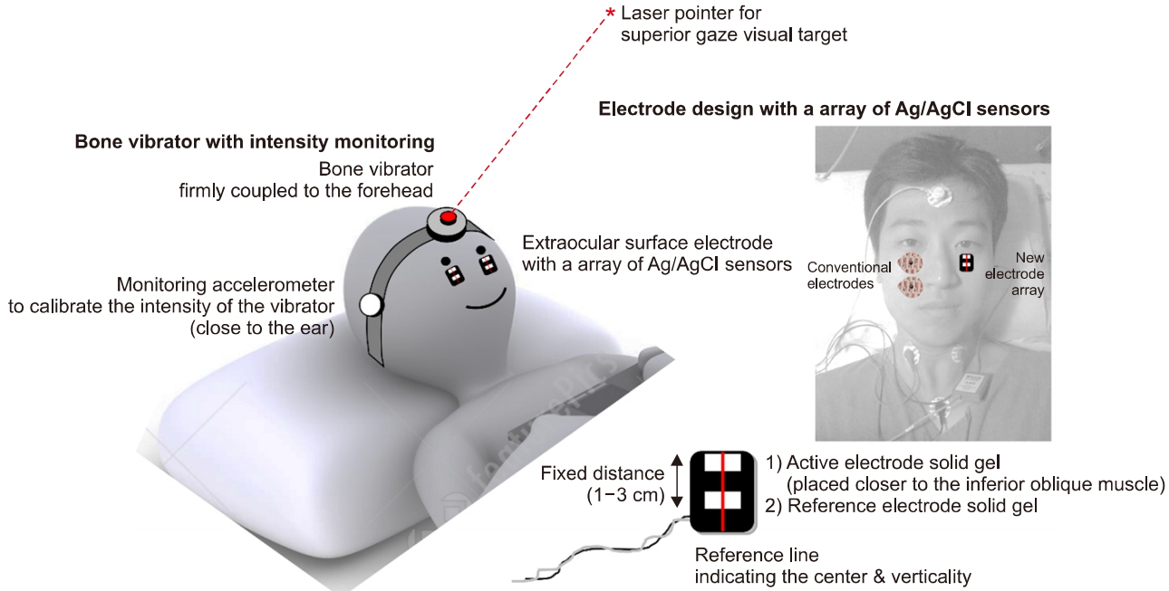
Proposal for development of an ocular vestibular evoked myogenic potential (oVEMP) recording system. The bone vibrator should be firmly coupled to the head. A monitoring accelerometer may be beneficial in that the intensity of the vibrator can be calibrated. The forehead module can be composed of a bone vibrator and a laser pointer to indicate the visual target for superior gazing. The infraorbital electrode can be composed of an array of Ag/AgCl sensors (active and reference electrode). An active electrode can be placed closer to the inferior oblique muscle. Vertical and horizontal reference lines can be marked on the electrode to allow the user to easily compare the vertical and horizontal locations of the bilateral electrodes. The portrait right of the photograph has been entrusted by the person himself.
Improvements in the infraorbital electrodes are also required. The electrode should be placed as close as possible to the inferior oblique muscle. However, at the same time, the horizontal and vertical locations of the bilateral electrodes should be matched. That is, if the electrode on one side is vertically lower than that on the other side, it will result in a smaller n10–p15 amplitude. In addition, if one electrode is located horizontally off-center compared to the other side, it will result in a smaller n10–p15 amplitude. To minimize the variability and maximize the amplitude of n10–p15, an electrode array (vertically aligned active and reference electrode) can be combined as a single sticker-type surface electrode (Fig. 3). The distance from the active electrode to the reference electrode should be fixed to minimize variability. The conductive solid gel and Ag/AgCl sensors should not be placed in the center of the sticker; instead, they should be deviated upwards so that the first electrode (active electrode) can be placed closer to the inferior oblique muscle. Vertical and horizontal reference lines can be marked on the electrode to allow the user to easily compare the vertical and horizontal locations of the bilateral electrodes. As shown in Fig. 3, the position and size of the conventional electrodes and the newly designed electrode array can be compared within a subject. It is much easier to place the active and reference electrodes at consistent positions (thus reducing variability), and with the active electrode being closer to the inferior oblique muscle, using our novel electrode array.
COMBINING cVEMP AND oVEMP
One problem with both cVEMP and oVEMP is that it takes a long time to record the response. Therefore, reducing the testing time would markedly improve the system. One method is to achieve this is to record cVEMP and oVEMP simultaneously [23]. For example, 500-Hz air-conducted sound (ACS) can be presented to the right ear as the stimulus. While cVEMP p13–n23 is being recorded from the right SCM muscle, oVEMP n10–p15 can be recorded from the left eye at the same time with the same stimulus. This may reduce the testing time by half. The same strategy may also be applied when bone-conducted vibration (BCV) is used as the stimulus.
Another point that should be noted is that the cVEMP response does not originate purely from the saccule. In addition, the oVEMP response does not originate purely from the utricle; which otolith organ is the origin of cVEMP and oVEMP has long been a matter of debate, and this issue has yet to be clarified in humans. For 500-Hz ACS, cVEMP is of 74% saccular origin and 26% utricular origin [24], while for 500-Hz BCV, cVEMP is of 61% saccular origin and 39% utricular origin. For 500-Hz ACS, oVEMP is of 32% saccular origin and 68% utricular origin, while for 500-Hz BCV, oVEMP is of 20% saccular origin and 80% utricular origin. Accordingly, the assumptions made in most reports in the literature, i.e., that cVEMP represents saccular function and oVEMP represents utricular function may not be true. It may be more accurate to interpret cVEMP and oVEMP together as the “otolith function.” For future evoked response systems, the final report of VEMP may indicate this point, so that the end users will not be misled. Another novel approach is to separate the saccular contribution from the utricular contribution by an independent component analysis (ICA, a computational method for separating a multivariate signal into additive subcomponents). By recording and combining ACS cVEMP/oVEMP and BCV cVEMP/oVEMP together, it may be possible to mathematically separate the components of each otolith organ. We may be able to refer to the independent saccular function and independent utricular function, only when the future evoked response systems are equipped with the VEMP response ICA functionality.
CONCLUSIONS
Both cVEMP and oVEMP have many drawbacks when compared to the more well-known vestibular function tests. The cVEMP and oVEMP results are inconsistent and unreliable in some cases. In addition, the reproducibility is questionable due to the large number of contributing factors. Some shortcomings, including unclear origin of the response, are fundamental problems. However, many of the other shortcomings can be improved by developing better recording methods and devices. The next several years will be very important for the future of VEMP. Many novel vestibular tests, such as the cochlear hydrops analysis masking procedure (CHAMP) [25] and electrocochleography [26], have been developed but end users have not adopted these new methods due to a lack of benefit over the original tests. VEMP seems to have a better chance, because there are no clinically available tests that can evaluate the function of the saccule and because there is firm evidence that VEMP is at least reliable for diagnosis of superior canal dehiscence syndrome [2]. VEMP will probably survive the harsh validation process, but not in its current form. Further research and development is needed to make VEMP a more consistent and reliable test.
Notes
No potential conflict of interest relevant to this article was reported.
Acknowledgements
This research was supported by the Korea Health Industry Development Institute (KHDI) of Korean Ministry of Health and Welfare (HI18C0626).